.jpg)
|
Ningbo Eurotec Precision Industry Co., Ltd.
|
ADP Withdrawal Sleeve AH3 Series
| Payment Terms: | T/T,L/C |
| Place of Origin: | Zhejiang, China (Mainland) |
|
|
|
| Add to My Favorites | |
| HiSupplier Escrow |
Product Detail
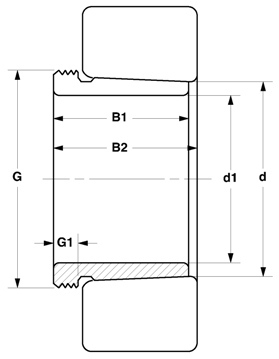
ADP withdrawal sleeves can be used to mount bearings with a tapered bore on cylindrical seats of stepped shafts.
Withdrawal Sleeve AH308-AHX322

| Designation | G | d1 | d | G1 | B1 | B2 |
| AH308 | M45×1.5 | 35 | 40 | 6 | 29 | 32 |
| AH309 | M50×1.5 | 40 | 45 | 6 | 31 | 34 |
| AHX310 | M55×2 | 45 | 50 | 7 | 35 | 38 |
| AHX311 | M60×2 | 50 | 55 | 7 | 37 | 40 |
| AHX312 | M65×2 | 55 | 60 | 8 | 40 | 43 |
| AH313 | M75×2 | 60 | 65 | 8 | 42 | 45 |
| AH314 | M80×2 | 65 | 70 | 8 | 43 | 47 |
| AH315 | M85×2 | 70 | 75 | 8 | 45 | 49 |
| AH316 | M90×2 | 75 | 80 | 8 | 48 | 52 |
| AHX317 | M95×2 | 80 | 85 | 9 | 52 | 56 |
| AHX318 | M100×2 | 85 | 90 | 9 | 53 | 57 |
| AHX319 | M105×2 | 90 | 95 | 10 | 57 | 61 |
| AHX320 | M110×2 | 95 | 100 | 10 | 59 | 63 |
| AHX321 | M115×2 | 100 | 105 | 12 | 62 | 66 |
| AHX322 | M120×2 | 105 | 110 | 12 | 63 | 67 |
ADP withdrawal sleeves can be used to mount bearings with a tapered bore on cylindrical seats of stepped shafts. The sleeve is pressed into the bore of the bearing that abuts a shaft shoulder or similar fixedcomponent. The sleeve is located on the shaft by a nut or an end plate. Lock nuts or endplates are not supplied with the extraction sleeves. KM or HM lock nuts and respective locking washers are suitable but must be ordered separately. Further information will be found in the section "Lock nuts with locking washer or clip".To secure the bearing to the shaft, press the extraction sleeve into the bearing bore. To do this, particularly where larger bearings are concerned, considerable force is required to overcome the friction between the mating surfaces of the bearing and sleeve and of the sleeve and shaft. Mounting and dismounting of bearings on extraction sleeves can be facilitated considerably by using a hydraulic nut .
Basic design
ADP extraction sleeves are slotted and have an external taper of 1:12 except for those in the A(O)H 240 and A(O)H 241 series which have an external taper of 1:30 and are intended for use with wide bearings in the 40 and 41 Dimension Series.
The nuts required for dismounting the extraction sleeve are not supplied with the sleeve and must be ordered separately. Appropriate sizes are listed in the product table. Appropriate hydraulic nuts for dismounting are listed there as well.
Design for hydraulic mounting
To enable the hydraulic mounting to be used for mounting and dismounting, ADP extraction sleeves with bore diameters of 200 mm and above are produced as standard with oil supply ducts and distributor grooves. 
These AOH sleeves have two oil supply ducts at the threaded side as well as oil distributor grooves in the circumferential and axial directions, both in the outside surface and the sleeve bore. If oil is injected through these ducts and grooves, an oil fil is formed between the mating surfaces of the bearing and sleeve and between the shaft and sleeve, and the force required to mount the bearing is considerably reduced. Details of the thread for attaching the oil supply lead to the ducts as well as of appropriate hydraulic nuts can be found in the product table.
Materials
The materials using in ADP extraction sleeves are carbon steel with a tensile strength at least 430N /mm2.
Dimensions
The dimensions of ADP extraction sleeves are in accordance with ISO 2982-1:1995.
Tolerances
The bore diameter of ADP extraction sleeves is to tolerance JS9, the width to h13.
Thread
ADP extraction sleeves up to size 38 have metric threads with 6g tolerances according to ISO 965-3:1998. Larger extraction sleeves have metric trapezoidal threads with 7e tolerance according to ISO 2903:1993.If standard nuts are not used, the threads of nuts for extraction sleeves up to size 38 should correspond to tolerance 5H according to ISO 965-3:1998. The threads of nuts for larger extraction sleeves should correspond to tolerance 7H according to ISO 2903:1993.
Shaft tolerances
As extraction sleeves adapt themselves to the shaft diameter, wider diameter tolerances can be permitted than for the seating of a bearing with a cylindrical bore. However, the form tolerances must be kept within narrow limits as the accuracy of form directly affects the running accuracy of the bearing. Generally, shafts should be machined to an h9 tolerance but the cylindricity should be to IT5/2 according to ISO 1101:2004.

.jpg)
.jpg)
.jpg)
.jpg)
.jpg)
.jpg)
.jpg)
