.jpg)
|
Ningbo Eurotec Precision Industry Co., Ltd.
|
roller conveyor bearing Mounting
| Payment Terms: | T/T,L/C |
| Place of Origin: | Zhejiang, China (Mainland) |
|
|
|
| Add to My Favorites | |
| HiSupplier Escrow |
Product Detail
HMVC18,HMVC19,HMVC20,HMVC21,HMVC22,HMVC24,HMVC26,HMVC28HMVC30,HMVC32,HMVC34,HMVC36,HMVC38,HMVC40,HMVC44,HMVC48HMVC52,HMVC56,HMVC60,HMVC64,HMVC68HMVC72
Design Principle
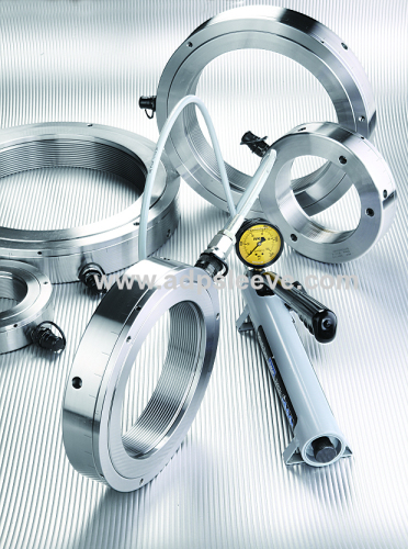
ADP hydraulic nut consist of an annular body, and a piston, in addition to the above main parts, there is a measuring ring which is the center of our innovation. The piston is operated hydraulically. The pressure chamber is sealed by two O-rings ofNitrile butadiene rubber (NBR).
The hydraulic nut are designed for a maximum oil pressure of 100 MPa (1000 bar or 14500 psi).Their stoke is power enough that the rolling bearings or other parts can be mounted in a single operation.
The bore G in the annular body is available with a metric fine thread, a trapezoidal thread or an inch thread. They are suitable for sleeve and shaft threadsof international standard.
ADP hydraulic nuts feature two oil supply connection holes with G 1/4 thread. Four handling holes are on the outside diameter of the annular body and two handling holes are on the side face for easier handling.
a) Design for accurate measurement of the piston travel:
To differentiate our add-on value from competitors, we focused on practicality and simplicity. Our idea was to build in a kind of " micrometer " onto the hydraulic nut so that there is no need for additional measuring instrument during installation. And this has been achieved by introducing a rotatable " measuring ring " on the outer rim of the piston via male and female threads. There are calibrations on the outer diameters of the annular body as well as the measuring ring. By adjusting and aligning calibrations on the opposite sides of annular body and measuring ring, the required axial drive-up can be achieved with ease within 0.015mm allowance of accuracy. The finer the thread pitch is the more precision it is going to give.

At the same time with the verification processes of our innovative ADP hydraulic nut with measuring ring, we've compared our product against competitors', which more or less adopting a design of an added-on dial gauge. During assembling of a hydraulic nut, it is very common that jerking takes place (especially when axial drive-up pressure exceeding 20 MPa) whenever there is a breakaway from overcoming static friction into sliding. Dial gauge with a nature of inaccuracy under jerking performs badly. Our product, on the contrary, proves to be influence-free from jerking.
b) Design for easy disassembly and maintenance:
In terms of maintenance, O-ring is the most consumed part and needs to be replaced anew once damaged. Our design of measuring ring provides an additional advantage over competitors'—jacking bolts do not intrude into annular body cavity. Intrusion by jacking bolts may create complication of compromising static sealing of the plug, which is important for constant high oil pressure application. With our design, there are three (3) jacking bolts equally spaced on the measuring ring. Upon disassembly for the replacement of O-ring these three jacking bolts are exactly the only tool and procedure need to be done, reliable and time-saving.
c) Flexible in both directions of installation:
Our measuring ring provides no interference in both directions during installation, i.e. the same hydraulic nut can be used for mounting and dismounting of withdrawal sleeve.

How it works
Example 1: Mounting a spherical roller bearing with adapter sleeve, 22320 K (see Step 1 to Step 5 by diagrammatic explanation). Theoretically, the axial drive-up for mounting it on a taper seating is 1.06 mm according to the calculation (the required max. radial internal clearancereduction is 0.06% of the nominal diameter of the bearing bore). In fact, due to the quality and the manufacturing allowances involved with shaft and adapter sleeve, there are variations in the total clearance before installation. And in practice, those variations can be eliminated by applying a pre-load pressure, which is 7.1 MPa (71 bar) more or less, in the hydraulic nut. After that, a further 0.92 mm in axial drive-up needs to be accomplished.
The thread pitch of the measuring ring is 1 mm. 0.92 mm in axial drive-up is converted into angular travel by the following simple equation:0.92÷1.00×360=331.2°≈330° As demonstrated by the following illustrations and steps, one can see how easily this can be done.
The example above mentioned is for the convenience diagrammatic explanation . In fact, for mounting spherical roller bearing 22320K with adapter sleeve H2320, two sliding surfaces, the initial preload is 8.7 MPa, a further 0.65 mm in axial drive-up needs to be accomplished . The thread pitch of the measuring ring is 1.5 mm. 0.65 mm in axial drive-up is converted into angular travel 155° . See the mounting data on Table 1.
Example 2, for mounting bearing 23164K with withdrawal sleeve AHX3164G which has two sliding surfaces, an ADP hydraulic nut HMV68E is used, the initial preload is 7.8 MPa, a further 1.85 mm in axial drive-up needs to be accomplished . The thread pitch of the measuring ring is 2 mm. 1.85 mm in axial drive-up is converted into angular travel 334°. This hydraulic nut can be used for extracting the sleeve in the same time. See the mounting data on Table 2.
Table 1 and Table 2 are our proposal which aim for the total reduction ofinternal clearance is 0.05% -0.055%of the nominal diameter of the bearing bore. (The variations depend on the section heightof the inner ring ofbearing design.)
Mounting Procedures
All the mounting data ofare listed on Table 1 and Table 2 which is very important for accurate mounting of spherical roller bearing with taper bore.It is very simple to use the data on the Tables:
-Depend on sleeve types, choose Table 1 or Table 2
-Select the sliding surface, single or double
-Find the preload pressure
-Choose the angular travel range

1-1Screw in the ADP hydraulic nut on the thread of the adapter sleeve and rotate the hydraulic nut with the help of a steel pin inserted on the outer rim of the annular body until the bearing is tightened by the hydraulic nut.
1-2Open the valve of the hydraulic pump.
1-3 Connect the high-pressure hose of hydraulic pump to the quick connecting nipple on the hydraulic nut. 1-4 Make sure again that the bearing is tightened against by the hydraulic nut.
1-5 Close the valve of the hydraulic pump to prevent the oil from back-flowing.

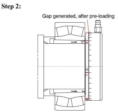
Pump the oil pressure up to 70 bar (7 Mpa). There will be a gap resulted from the axial movement of the piston when jacking up the oil pressure. It doesn't matter how big or small the gap is.

3-1Insert a Φ5 mm pin into the hole on the outer rim of the measuring ring and rotate it to tighten against the annular body.
3-2Mark one of the calibrations on the measuring ring as the reference starting point. In this example, index no.1 is specified.
3-3Locate a mark 330° away from the reference starting point in step 3-2 on the calibrations of the cylinder as the target mark. Aligning the reference starting point (index no.1) with the target mark will have the job done.

Continue to pump the oil to an appropriate incremental pressure. There will be a growing gap between measuring ring and annular body. Stop pumping and rotate the measuring ring to close the gap. Watch how far you need to go between the reference starting point (index no.1) and the target mark.

Repeat step 4 in graduation until alignment of the reference starting point and the target is reached.
Threads
ADP hydraulic nuts up to and including size 40 have metric ISO threads to tolerance 6H(ISO 965/III-1980)and the lager nuts from size 41 have metric ISO trapezoidal threads to tolerance 7H (ISO 2901-1977).
The mating thread on the shaft should made to the tolerance 6g (ISO 965/III-1980) for the small sizes, and tolerance 7e (ISO 2901/1977) for sizes with trapezoidal thread.
Material
The annular body of ADP hydraulic nuts up to and including size 64 are made ofhardenable steel and the pistons are made of bearing steel. From size 66 the annular bodys and pistons are made of Grade 2 construction steel.
ADP hydraulic nut consist of an annular body, and a piston, in addition to the above main parts, there is a measuring ring which is the center of our innovation. The piston is operated hydraulically. The pressure chamber is sealed by two O-rings ofNitrile butadiene rubber (NBR).
The hydraulic nut are designed for a maximum oil pressure of 100 MPa (1000 bar or 14500 psi).Their stoke is power enough that the rolling bearings or other parts can be mounted in a single operation.
The bore G in the annular body is available with a metric fine thread, a trapezoidal thread or an inch thread. They are suitable for sleeve and shaft threadsof international standard.
ADP hydraulic nuts feature two oil supply connection holes with G 1/4 thread. Four handling holes are on the outside diameter of the annular body and two handling holes are on the side face for easier handling.
a) Design for accurate measurement of the piston travel:
To differentiate our add-on value from competitors, we focused on practicality and simplicity. Our idea was to build in a kind of " micrometer " onto the hydraulic nut so that there is no need for additional measuring instrument during installation. And this has been achieved by introducing a rotatable " measuring ring " on the outer rim of the piston via male and female threads. There are calibrations on the outer diameters of the annular body as well as the measuring ring. By adjusting and aligning calibrations on the opposite sides of annular body and measuring ring, the required axial drive-up can be achieved with ease within 0.015mm allowance of accuracy. The finer the thread pitch is the more precision it is going to give.

At the same time with the verification processes of our innovative ADP hydraulic nut with measuring ring, we've compared our product against competitors', which more or less adopting a design of an added-on dial gauge. During assembling of a hydraulic nut, it is very common that jerking takes place (especially when axial drive-up pressure exceeding 20 MPa) whenever there is a breakaway from overcoming static friction into sliding. Dial gauge with a nature of inaccuracy under jerking performs badly. Our product, on the contrary, proves to be influence-free from jerking.
b) Design for easy disassembly and maintenance:
In terms of maintenance, O-ring is the most consumed part and needs to be replaced anew once damaged. Our design of measuring ring provides an additional advantage over competitors'—jacking bolts do not intrude into annular body cavity. Intrusion by jacking bolts may create complication of compromising static sealing of the plug, which is important for constant high oil pressure application. With our design, there are three (3) jacking bolts equally spaced on the measuring ring. Upon disassembly for the replacement of O-ring these three jacking bolts are exactly the only tool and procedure need to be done, reliable and time-saving.
c) Flexible in both directions of installation:
Our measuring ring provides no interference in both directions during installation, i.e. the same hydraulic nut can be used for mounting and dismounting of withdrawal sleeve.

How it works
Example 1: Mounting a spherical roller bearing with adapter sleeve, 22320 K (see Step 1 to Step 5 by diagrammatic explanation). Theoretically, the axial drive-up for mounting it on a taper seating is 1.06 mm according to the calculation (the required max. radial internal clearancereduction is 0.06% of the nominal diameter of the bearing bore). In fact, due to the quality and the manufacturing allowances involved with shaft and adapter sleeve, there are variations in the total clearance before installation. And in practice, those variations can be eliminated by applying a pre-load pressure, which is 7.1 MPa (71 bar) more or less, in the hydraulic nut. After that, a further 0.92 mm in axial drive-up needs to be accomplished.
The thread pitch of the measuring ring is 1 mm. 0.92 mm in axial drive-up is converted into angular travel by the following simple equation:0.92÷1.00×360=331.2°≈330° As demonstrated by the following illustrations and steps, one can see how easily this can be done.
The example above mentioned is for the convenience diagrammatic explanation . In fact, for mounting spherical roller bearing 22320K with adapter sleeve H2320, two sliding surfaces, the initial preload is 8.7 MPa, a further 0.65 mm in axial drive-up needs to be accomplished . The thread pitch of the measuring ring is 1.5 mm. 0.65 mm in axial drive-up is converted into angular travel 155° . See the mounting data on Table 1.
Example 2, for mounting bearing 23164K with withdrawal sleeve AHX3164G which has two sliding surfaces, an ADP hydraulic nut HMV68E is used, the initial preload is 7.8 MPa, a further 1.85 mm in axial drive-up needs to be accomplished . The thread pitch of the measuring ring is 2 mm. 1.85 mm in axial drive-up is converted into angular travel 334°. This hydraulic nut can be used for extracting the sleeve in the same time. See the mounting data on Table 2.
Table 1 and Table 2 are our proposal which aim for the total reduction ofinternal clearance is 0.05% -0.055%of the nominal diameter of the bearing bore. (The variations depend on the section heightof the inner ring ofbearing design.)
Mounting Procedures
All the mounting data ofare listed on Table 1 and Table 2 which is very important for accurate mounting of spherical roller bearing with taper bore.It is very simple to use the data on the Tables:
-Depend on sleeve types, choose Table 1 or Table 2
-Select the sliding surface, single or double
-Find the preload pressure
-Choose the angular travel range

1-1Screw in the ADP hydraulic nut on the thread of the adapter sleeve and rotate the hydraulic nut with the help of a steel pin inserted on the outer rim of the annular body until the bearing is tightened by the hydraulic nut.
1-2Open the valve of the hydraulic pump.
1-3 Connect the high-pressure hose of hydraulic pump to the quick connecting nipple on the hydraulic nut. 1-4 Make sure again that the bearing is tightened against by the hydraulic nut.
1-5 Close the valve of the hydraulic pump to prevent the oil from back-flowing.

Pump the oil pressure up to 70 bar (7 Mpa). There will be a gap resulted from the axial movement of the piston when jacking up the oil pressure. It doesn't matter how big or small the gap is.

3-1Insert a Φ5 mm pin into the hole on the outer rim of the measuring ring and rotate it to tighten against the annular body.
3-2Mark one of the calibrations on the measuring ring as the reference starting point. In this example, index no.1 is specified.
3-3Locate a mark 330° away from the reference starting point in step 3-2 on the calibrations of the cylinder as the target mark. Aligning the reference starting point (index no.1) with the target mark will have the job done.

Continue to pump the oil to an appropriate incremental pressure. There will be a growing gap between measuring ring and annular body. Stop pumping and rotate the measuring ring to close the gap. Watch how far you need to go between the reference starting point (index no.1) and the target mark.

Repeat step 4 in graduation until alignment of the reference starting point and the target is reached.
Threads
ADP hydraulic nuts up to and including size 40 have metric ISO threads to tolerance 6H(ISO 965/III-1980)and the lager nuts from size 41 have metric ISO trapezoidal threads to tolerance 7H (ISO 2901-1977).
The mating thread on the shaft should made to the tolerance 6g (ISO 965/III-1980) for the small sizes, and tolerance 7e (ISO 2901/1977) for sizes with trapezoidal thread.
Material
The annular body of ADP hydraulic nuts up to and including size 64 are made ofhardenable steel and the pistons are made of bearing steel. From size 66 the annular bodys and pistons are made of Grade 2 construction steel.
Didn't find what you're looking for?
Post Buying Lead or contact
HiSupplier Customer Service Center
for help!
Related Search
Conveyor Roller
Roller Conveyor
Conveyor Bearing
Roller Bearing
Roller Conveyor Chain
Pvc Conveyor Roller
More>>


.jpg)
